EverTag User Guide

Contents
1 Introduction to the EverTag Series 4
7 Configuration using CB-admin 14
7.2.1 Anchor tampering detecton 14
7.2.2 NFC pin code protection 15
7.5 Beaconing - CargoBeacon config 16
7.6 Beaconing - iBeacon config 17
7.7 Beaconing - GATT Service Beacon (GBCN) config 17
7.8 Multiple Beacons - Scheduling Behavior 18
8 Configuration over Wirepas network 19
8.2 Application configuration 22
8.2.1 Packet Field Definitions 22
8.2.2 Packet payload Definitions 23
8.2.3 Configuration command examples 25
8.3 How to send configuration data 27
9 Tag events over Wirepas network 28
14 Declaration of conformity 34
14.1 Federal Communications Commission (FCC) for US 34
14.1.1 FCC RF Exposure compliance 34
14.2 Innovation, Science, and Economic Development (ISED) for Canada 35
Introduction to the EverTag Series
The EverTag family includes two product series: EverTag Mesh and EverTag Mesh Mini. This manual explains how to use these products and covers key variants from each series.
EverTag Mesh products have article numbers starting with 230 xxx. The base model in this series is 230010. Other models included in this manual are EverTag-T and EverTag-SL.
EverTag Mesh Mini products have article numbers starting with 231 xxx. The base model in this series is 231010.
Refer to the table below for a quick overview:
Series |
Product Name |
Article Number |
|---|---|---|
EverTag Mesh |
Base Model |
230010 |
EverTag-T |
230012 |
|
EverTag-SL |
230015 |
|
EverTag Mesh Mini |
Base Model |
231010 |
This manual will help you set up and use these EverTag devices effectively for your needs.
References
Wirepas developer documentation https://developer.wirepas.com/
Wirepas gateway to backend documentation https://github.com/wirepas/backend-apis/blob/master/gateway_to_backend/README.md
Using the Wirepas gateway API https://developer.wirepas.com/support/solutions/articles/77000487992-how-to-communicate-with-a-wirepas-network-using-wirepas-gateway-api
Wirepas Network Tool v4 Client User Guide https://developer.wirepas.com/support/solutions/articles/77000499190-wirepas-network-tool-v4-client-user-guide
Symbols and figures
The following symbols are used for clarifications of contents
⚠️ |
Exclamation mark is used to highlight extra important information. |
|---|---|
🔍 |
A magnifying glass is used to highlight differences between different products and options in comparisons. |
Abbreviations
LUT |
Look up table |
|---|---|
WM |
Wirepas Mesh |
SDK |
Software Development Kit |
Document revision
Revision |
Change |
Date |
|---|---|---|
1.7 |
Corrections for SL |
250702 |
1.6 |
Corrections for EverTag T and SL |
250618 |
1.5 |
Added section about multi vendor support |
250115 |
1.4 |
Updates to cover EverTag Mini mesh family |
241205 |
1.31 |
Document rename and updates around EverTag-SL. |
240820 |
1.21 |
Updates around EverTag-T |
240614 |
1.11 |
Updates around multitap, NFC pin and profile settings. Updated app screenshots. |
240430 |
1.0 |
Release after review of v0.11. |
231101 |
Wirepas Mesh
Wirepas Mesh is a decentralized wireless mesh networking technology that enables large-scale IoT deployments with minimal infrastructure. It allows devices to communicate directly with each other, forming a self-organizing and self-healing network that can scale to millions of devices.
It uses ultra-low-power wireless communication, making it suitable for battery-powered devices and reducing the need for frequent battery replacements. It also provides low latency and high reliability, making it suitable for real-time industrial applications such as asset tracking.
Wirepas Mesh works well for industrial asset tracking because it can accurately locate and track assets in challenging environments such as warehouses, factories, and outdoor areas. It can also provide real-time information about asset location, movement, and condition, enabling better inventory management, maintenance planning, and supply chain optimization.
It is a flexible and open technology that can be integrated with various sensors, gateways, and cloud platforms. This enables businesses to create custom IoT solutions that meet their specific needs and requirements, while also enabling interoperability and scalability across different applications and use cases.
Mesh in asset tracking
A typical installation for a manufacturing site would typically look like below:

Component |
Role |
Description |
|---|---|---|
🔵 |
Anchor |
EverTag configured as anchor |
⚪ |
Sink |
Also known as Wirepas gateway or mesh gateway. |
🟢 |
Tag |
EverTag configured as tag NRLS |
Anchors
In a Wirepas Mesh network, an anchor is a device that provides fixed location information to other devices in the network.
Anchors are typically stationary devices with known and fixed locations, such as access points or gateways. By providing the IoT infrastructure and location information to other devices, anchors enable accurate asset tracking and location-based services within the network.
Sink A sink is a device that serves as a gateway between the mesh network and an external network, such as the internet or a local server. Sink may sometimes also be referred to as “Wirepas gateway” or “mesh gateway”.
Tag A tag is a small, low-power device that can be attached to an asset to enable its tracking and monitoring. Tags communicate with other devices in the mesh network to determine their location and transmit data about their condition, movement, or other relevant parameters.
Tags are typically battery-powered and have a long battery life, making them suitable for use in asset tracking applications.
EverTag multi-vendor network support
The DECT-2020 NR standard ensures that EverTag devices provide:
Interoperability: Devices from different vendors can function together in the same network.
Scalability: Supports large-scale deployments by allocating unique and conflict-free endpoints.
Reliability: Aligns with industry standards to ensure robust communication.
Future Compatibility: Prepared for evolving connectivity and use cases.
By adhering to these standards, EverTag enables robust operation in multi-vendor networks, ensuring dependable performance in diverse environments. CargoBeacon has been assigned ID 0xA06B to 0xA06F.
Endpoint Value construction
Endpoints are 16-bit identifiers used for routing messages within Wirepas Mesh networks. ETSI assigns endpoints from the range 0xA000 to 0xBFFF for company-specific use. This allocation guarantees unique and conflict-free communication. CargoBeacon use endpoint 0xA06B for messaging using
Source Endpoint (MSB): 0xA0
Destination Endpoint (LSB): 0x6B
Applicability: This endpoint value construction applies to:
EverTag Mini - all versions
EverTag - from firmware version 2.0.5 and onwards.
Application Area ID Construction
The Application Area ID uniquely identifies device applications and hardware. It is derived from the DECT-2020 NR endpoint and includes:
Prefix (0x9): Application-level identifier.
Endpoint (0xA06C): ETSI-assigned company endpoint.
OEM Range (0x01): Differentiates between applications within the company’s scope.
Reserved (0x00): Reserved for future extensions.
Applicability: This application area ID construction applies to:
EverTag Mini - all versions
The Application Area ID 0x12A205 is retained for existing EverTag variants to maintain compatibility with Over-The-Air Programming (OTAP). The new construction applies only to updated products, such as EverTag Mini, ensuring consistent operation across the product line.
Use cases
The asset tag firmware is dynamic in nature and can be configured to support multiple use cases. The following list includes but not limited to the use cases supported by the EverTag series.
Asset tracking
The Wirepas positioning application will be used to accurately track the indoor location of the assets tag is attached to. As the Tag-ID is also encoded into beaconing data. It enables asset tracking applications outside Wirepas mesh such as smartphone applications and IoT gateways.
Utilization rate
The internal accelerometer detects movements and controls an internal state machine. Movement information is shared over beaconing and over Wirepas backend. This movement information is locally stored and may be used to estimate the utilization of the asset. With movement information at hand, you may work to improve the utilization rate of tools and similar assets by better allocation.
Smart load carrier
Press the tag button set the tag into alert-state. The alert state is sent over beaconing and Wirepas backend. This may be used to indicate a load carrier is being ready for pick-up or that “work-in-progress” material is ready for next process.
Pick-by-light scenarios
The tag LED can be commanded to emit or blink according to a desired pattern. The typical use-case could be to blink a few milliseconds per second when looking for a specific asset located among others.
Intelligent anchor
The device has been designed to suit well both for operation in tag role as well as anchor role. As an anchor it is equipped with a button it may be used to trigger a maintenance activity or any other activity needed in the proximity of the anchor.
Tampering detection
Unauthorized movement of an installed anchor can be disastrous for many types of applications. For this reason, the device continuously monitors potential tampering activities. An anchor will report any movements detected to the backend so that a warning may be issued. See tampering-detection in Table 3.
EverTag mesh - roles
The EverTag series has been developed for battery powered asset tracking use cases and therefore support all relevant roles. See Wirepas developer documentation for further details.
Anchor - opportunistic
⚠️ The “Anchor -opportunistic” mode is the recommended mode to be used for a battery-operated anchor.
A stationary tag placed at a known location in the network. These tags are connected at all times, to the Wirepas Mesh (WM) network. For the purpose of maintaining the connectivity the WM stack will perform network scans in order to detect Router/Sink nodes in the vicinity. The positioning app will collect and send the measurements generated by these scans, thus the opportunistic mode. Given that the positioning app does not trigger additional scans the power impact on the anchor is minimal (only the cost of sending a data packet).
Tag - NRLS
⚠️ The “Tag NRLS” mode is the recommended mode for a standard asset tracking tag.
In the Non-Router Long Sleep (NRLS) mode the tag is in sleep mode between two measurement updates. The tag will wake up at periodic configurable intervals and: perform a network scan, connect to WM, send the collected measurements, receive application configuration, disconnect from WM and finally go into sleep.
In this mode the positioning app does not trigger a network scan and the scan performed by the WM stack (required for establishing the connectivity) is used for collecting the RSSI measurements.
The disadvantage is that the tag cannot receive data while in sleep. The application configuration is used to provide configuration updates to the tag at wakeup.
Tag - Auto scan
The “Tag - Auto scan” mode is only recommended for use-cases where the application requires continuous connectivity to the Wirepas Mesh network.
This could be a pick to light scenario where there is the requirement to send and receive data packets at random times. As the tag maintains the connectivity, the power consumption is higher than of the NRLS mode, especially when the tag is moving around.
Provisioning
Tag manufacturing has been setup to support custom provisioning parameters per customer. Contact CargoBeacon for volume deliveries using custom configuration / adaptations.
On delivery the tag will be configured with its default provisioning parameters:
Provisioning parameters |
Setting |
|---|---|
Power enable |
Off |
Open Joining enable |
Off |
Role |
Tag - NRLS |
Tag Class |
250 |
Channel ID |
5 |
Network ID |
56974 |
Table 1. Default provisioning parameters
For a quick start the tag may be configured with the CB-admin app over NFC. Find the apps here:
CB-admin on Google Play link
CB-admin on Apple App-store link.
A delivered tag will per default be in off-mode. Press and hold the button for more than 5 seconds when in off-mode and the tag will wake up to initiate the provisioning procedure. A first blink will indicate button press and a second blink will indicate power enable.
Positioning application
The positioning application for Wirepas-enabled devices, runs on both anchor and tag roles. It introduces a series of advanced functionalities, and allows to manage the positioning interval of moving tags on the basis of motion status in order to get an optimal compromise between battery life and refresh rate. Positioning app also allows to configure optional smartphone beaconing functionality.
Finite-State Machine
The positioning application implements a Finite-State Machine (FSM) for moving tags, based on 5 different states. The FSM optimizes power consumption by adjusting positioning intervals based on the tag’s current activity.
State Descriptions
🔴 OFF State
Tag is delivered in off state to minimize power consumption
No radio, LED, or other functionalities enabled
Used for shelf storage
Press and hold button for more than 5 seconds to enter provisioning mode
🟡 PROVISIONING State
Tag enters this state directly upon startup
Open joining procedure is started
This state is skipped if “Open Join Enable” is set to false
Automatic network configuration occurs here
🟢 DEFAULT State
Startup and default operating state of the tag
Remains in this state when not moving and no alerts are triggered
Uses idle positioning interval (default: every 8 hours)
Lowest power consumption during normal operation
🔵 MOVEMENT State
Triggered by movement detection using the accelerometer
Uses faster positioning interval (default: every 2 minutes)
Returns to DEFAULT state after movement timeout (default: 30 seconds)
Balances tracking accuracy with power consumption
🔴 ALERT State
Triggered by alarm conditions (button press or commands)
Highest priority state
Uses fastest positioning interval (default: every 1 minute)
LED blinks during this state
Returns to DEFAULT state after alert timeout (default: 120 seconds)
The following scheme highlights individual states and state transitions. Scheme refers to a case where alert is triggered by button press.
 Figure 1. Application finite state machine
State Transitions
The state machine follows these transition rules:
OFF → PROVISIONING: Button press (>5 seconds) or power enable via NFC
PROVISIONING → DEFAULT: Successful network joining
DEFAULT → MOVEMENT: Accelerometer detects motion above threshold
DEFAULT → ALERT: Button press or remote alert command
MOVEMENT → DEFAULT: No motion detected for movement timeout period
MOVEMENT → ALERT: Button press or alert command (highest priority)
ALERT → DEFAULT: Alert timeout expires
Any State → OFF: Power disable command or button shutoff timeout
⚠️ Note: ALERT state has the highest priority and can be entered from any active state.
FSM Parameters
Parameter |
Definition |
|---|---|
DEFAULT_PI |
DEFAULT positioning interval. Default 28800 (every 8 hours). |
MOVEMENT_PI |
MOVEMENT state positioning interval. Default 120 (every two minutes). |
ALERT_PI |
ALERT state positioning interval. Default 60 (every one minute). |
MOVEMENT_TO |
Movement Timeout - returns to DEFAULT state. Default 30 seconds. |
ALERT_TO |
Alert Timeout - return to DEFAULT state. Default 120 seconds. |
ACC_THR |
Accelerometer threshold (for movement detection) |
BTN_SHUTOFF_TO |
Button shutoff timeout. Default 0 - never shutoff. |
Table 2. Finite state parameters.
All FSM parameters are configurable using Wirepas mesh backend or configurable using NFC.
Configuration using CB-admin
The tag may either be configured over NFC using the CB-admin app or over Wirepas backend using Wirepas Network Tool. The CB-admin app may also be utilized to detect and read smartphone beaconing information.
Power on
The tag is delivered in power off mode. To turn it on you have two options:
Either press and hold the button for 5 seconds. The tag will wake up and connect to the configured network.
Alternatively use your smartphone, connect over NFC and configure the “power enable” according to the instructions below.
To connect over NFC, first download and install the CargoBeacon CB-admin app from Google play
or Apple app store
.
Ensure to have NFC enabled on your phone. Read settings using NFC by approaching your phones NFC antenna against the tag QR code. Slightly move the tag around until the phone recognize the NFC tag and reading starts. This is usually indicated by a beep and/or a small vibration. Hold the tag still against your phone once reading.
|
|
|---|---|
Figure 2. EverTag |
Figure 3. EverTag mini |


Unique features
The EverTag family features advanced security and configuration tools designed to enhance the reliability and management of devices. These include Anchor Tampering Detection, NFC-Pin Code Protection, Multi-Tap Feature, and secure Profile Settings. All features can be configured using the CB-admin app and they are aimed at providing robust security and streamlined device management across various environments.
Anchor tampering detecton
To safeguard the accuracy of the positioning algorithm, it’s crucial to detect any tampering with anchors, as removed or misplaced anchors can lead to erroneous positioning data. This is particularly critical in remote locations where issues may only be identified through customer complaints. The anchor tampering detection feature monitors for any movement of the anchors and triggers a backend event. This prompt detection allows for proactive maintenance, thereby preventing potential problems and ensuring system integrity.
NFC pin code protection
For devices in publicly accessible or vulnerable environments, the NFC-pin code protection enhances security by requiring a pin code to access or modify device settings via NFC. This feature prevents unauthorized access, ensuring that all settings stored over NFC, which are protected using SHA-256 encryption, remain secure. The combination of NFC-pin code and anchor tampering detection significantly boosts the confidence in device security, maintaining the integrity of anchors even in high-risk areas.
Multi-Tap Feature
 The multi-tap feature in the CB-Admin app enhances the
efficiency of configuring settings across multiple EverTag devices. By
activating multi-tap mode, users can swiftly apply pre-set
configurations to each tag with minimal effort, streamlining the
deployment process.
The multi-tap feature in the CB-Admin app enhances the
efficiency of configuring settings across multiple EverTag devices. By
activating multi-tap mode, users can swiftly apply pre-set
configurations to each tag with minimal effort, streamlining the
deployment process.
This feature is especially beneficial for setting new passwords and encrypting settings across devices simultaneously, ensuring uniform security and consistency. A common scenario is when installing “on-site” and discovering that an additional number of anchors/ tags may be needed.
You will reach the multitap mode from the settings menu (three dots in the corner). Once in multitap mode checkboxes will appear before the settings you may write using multitap. To avoid mistakes, it is not possible to multitap the same tag ID or iBeacon major/minor onto multiple devices.
Tick the checkboxes for the settings you wish to store/modify and press “update multiple tags”. You may then tap the devices you wish to update with the selected settings.
Profile Settings
Profile settings in the CB-Admin app facilitate the easy creation and distribution of encrypted configuration files, allowing for consistent setups across projects and devices. These profiles, shareable both within an organization and with external partners, streamline deployments and maintain standardization. Enhanced security is ensured as all sensitive data within the profiles is encrypted, and access is strictly controlled through robust password protection, safeguarding against unauthorized modifications.
General config

Firmware version. This denotes the tag application firmware version. Read only.
Hardware version. This is the PCB hardware type. Read only.
Power Enable. Enable/disable tag power. Configurable over NFC and button (if button-shutoff is not 0).
Tag NFC pin. Secure the tag by requiring a pin code to access or modify device settings via NFC. The tag NFC pin must match the app NFC pin in order to read/write NFC settings. 8 characters required. Default: 12345678.
Battery level as read by software.
Current network status as determined by tag.
Network config

Open joining provisioning enable. This option enables the automatic selection of network address, network channel, tag role and tag class options below. Default disabled.
Tag Role: Can be either tag or anchor. Tag - NRLS, Tag - Autoscan or Anchor - opportunistic. Default Tag - NRLS.
Tag class. Using classes tags can be grouped into different functions. Class may range from 249 to 255. That this value is changed to 249 for anchor role and 250 for tag role but may be overridden if need. Default 250.
Network address. The mesh network address to connect to may be up to three bytes long. Applicable only if open joining is disabled. Default network address 56974.
Tag identifier. The mesh tag identifier may be up to 4 bytes long. For simple readability this ID defaults to the three least significant bytes of the BT-address. Note: modifying the tag identifier will also affect the value of the BT-address as used by beaconing advertisement data.
Beaconing - CargoBeacon config
This beaconing mode include additional tag information in terms of utilization and sensor data. See cbeacon-advertisement for detailed information.

Beaconing. Enable or disable the transmission of smartphone compatible advertisement frames.
Off. Don’t transmit advertisements. Most power efficient.
On. Always transmit advertisements.
No network. Transmit only if outside Wirepas network. Once disconnected from the network it takes approximately 30 minutes before smartphone beaconing occurs. Defaults to CBeacon Mode - off.
Beacon Tx power. Transmit power from -4dBm to +8dBm. Default 0dBm.
Beacon advertisement period. The periodicity of advertisements in milliseconds. Default 2000ms.
Beaconing - iBeacon config
The ibeacon mode may be used for way-finding applications or asset
tracking applications.

iBeacon Mode. Enable or disable the beaconing transmission.
Off. Don’t transmit advertisements. Most power efficient.
On. Always transmit advertisements.
No network. Transmit only if outside Wirepas network. Once disconnected from network it takes approximately 30 minutes before smartphone beaconing occur.
Defaults to iBeacon Mode - off.
iBeacon Tx power. Beacon transmits power from -4dBm to +8dBm.
Default 0dBm.
iBeacon interval. The periodicity of advertisements in milliseconds. Default 2000ms.
iBeacon UUID. A random number that may be changed on project basis. Default f2746fd6-483d-11ee-be56-0242ac120002.
iBeacon Major ID. Defaults to 0x00XX where XX is the third and most significant byte of the tagID.
iBeacon Minor ID. Defaults to 0xYYXX where YY is the second byte and XX is the first byte of the tagID.
Beaconing - GATT Service Beacon (GBCN) config
The GATT Service Beacon advertises a 128-bit service UUID, allowing the tag to be discovered by BLE central devices scanning for specific services.
Why GBCN? iOS Background Scanning
⚠️ Important for iOS apps: Apple iOS has strict limitations on BLE scanning when apps are in the background (screen off, app minimized).
Beacon Type |
Advertisement Data |
iOS Background Detection |
|---|---|---|
iBeacon |
Manufacturer data |
❌ Not visible* |
CBeacon |
Manufacturer data |
❌ Not visible |
GBCN |
Service UUID (0x07) |
✅ Works! |
* iBeacon works in iOS background only via Apple’s proprietary CLLocationManager API, which has significant restrictions (limited regions, delayed notifications).
How iOS CoreBluetooth works:
In foreground: Can scan for any BLE advertisement
In background: Can only wake up for specific 128-bit Service UUIDs
GBCN uses AD Type 0x07 (Complete 128-bit Service UUID), which iOS CoreBluetooth can detect even when the app is suspended. This makes GBCN essential for:
Asset tracking apps that need to detect tags with screen off
Hands-free workflows where users don’t actively use the phone
Any iOS deployment requiring reliable background detection
Recommendation: For cross-platform deployments with iOS background detection requirements, enable GBCN alongside iBeacon/CBeacon.
GBCN Configuration
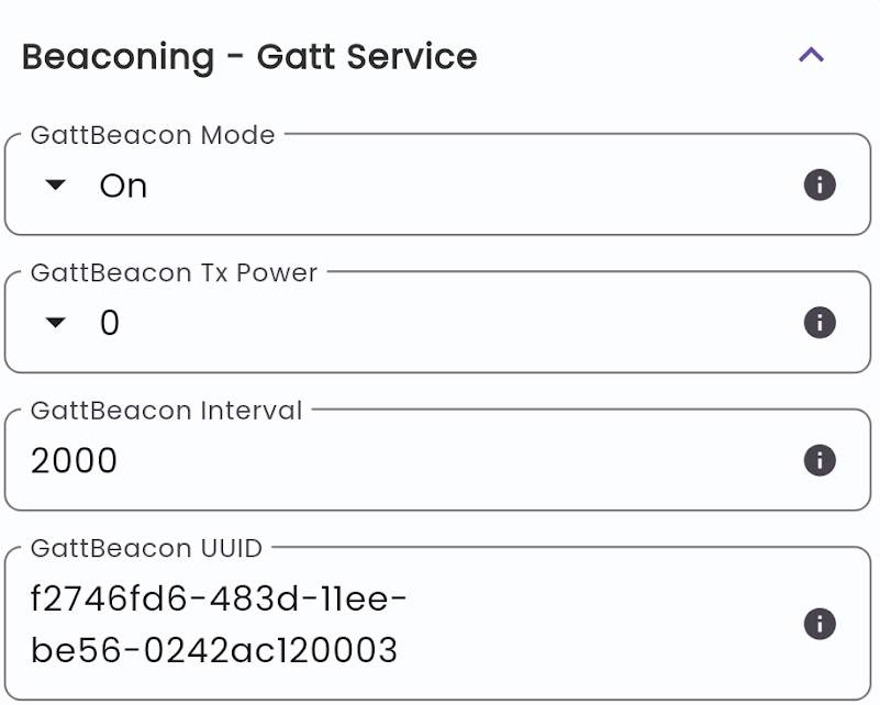
GBCN Mode. Enable or disable the GATT service beacon.
Off. Don’t transmit. Most power efficient.
On. Always transmit.
No network. Transmit only when disconnected from Wirepas network.
Defaults to GBCN Mode - off.
GBCN Tx power. Transmit power from -4dBm to +8dBm. Default 0dBm.
GBCN interval. The periodicity of advertisements in milliseconds. Default 2000ms.
GBCN UUID. The 128-bit service UUID to advertise.
Multiple Beacons - Scheduling Behavior
⚠️ Important: When multiple beacon types are enabled simultaneously (CBeacon, iBeacon, GBCN), they share the radio using round-robin scheduling.
How it works
The shortest configured interval is used as the base transmission rate.
Beacons are transmitted one at a time, cycling through enabled types.
Each beacon’s effective interval = base interval × number of enabled beacons.
Example
Configuration |
Base Interval |
Effective Interval per Beacon |
|---|---|---|
1 beacon @ 2s |
2s |
2s |
2 beacons @ 2s each |
2s |
4s (each) |
3 beacons @ 2s each |
2s |
6s (each) |
Power Consumption
Enabling multiple beacons does not multiply power consumption proportionally. The radio transmits at a fixed rate (the shortest interval); only the payload changes each cycle.
Beacons Enabled |
TX Events/6s |
Power Impact |
|---|---|---|
1 @ 2s |
3 |
Baseline |
3 @ 2s each |
3 |
~Same as baseline |
To achieve a specific advertisement rate per beacon type, divide your desired interval by the number of enabled beacon types.
Positioning interval

Idle positioning interval. The time between each positioning event when in default-state. Default 28800s (once every 8 hours).
Movement positioning interval. The time between each positioning event when in movement-state. Default 120s.
Alert positioning interval. The time between each positioning event when in alert state. Default 60s.
Tag configuration

Movement threshold. The threshold value to detect movement and set application into movement state. Default 800mG
Movement timeout. If movement is not detected within this timeout the tag returns to default-state. Default 30s.
Alert Timeout. The time before returning to default state in seconds. Default 120 seconds.
BloC Report interval. Business LOgiC report interval in minutes. The interval for reporting BloC data to backend. Default 60 minutes.
Button shutoff timeout. Number of seconds to press and hold the button to shutoff device. 0 disables the function. NOTE: The button shutoff is not active during tag ALERT state even if enabled. Default 0s.
Network keys config

Auth keys. Wirepas network authentication key. Recommended to be made unique on project basis. 16 byte hex character. Default 0xffff ffff ffff ffff
Encryption keys. Wirepas network encryption key. Recommended to be made unique on project basis. 16 byte hex character. Default 0xffff ffff ffff ffff
Configuration over Wirepas network
The tag takes use of Shared application as described in the Wirepas positioning application documentation. With this function an application configuration data message is sent to each node in the network. A node will receive the latest application configuration upon connection and every time the configuration is updated. This means you need to update the shared app config count number to ensure that the message sent is routed to all nodes in the network.
Note that a tag set in NRLS mode will only receive the application configuration when the tag wakes up for making a positioning update.
Network configuration
The tags support Wirepas remote configuration API to change network settings. This is particularly a useful feature if you want to re-program multiple devices with new network settings.
This example assumes you have a network configured with network ID 1457210 and wish to set network Id 56974 with network channel 5 (which is also the default tag setting). First, make sure all nodes that you wish to configure are powered on and connected to the network you wish to configure.
⚠️ Note: Configuration settings are persistent. They will be received and applied after the tag reboots.
Go to “Settings” -> “Node Configuration” and select the Broadcast tab. Add the items you would like to change. Here we change network address and network channel to the desired settings. Then click continue in the bottom right corner.

A new tab will open called “process”. Click “Start configuration” and wait until responses are received from all nodes in the scope.

Wait until responses have been received from all nodes and click “Start Activation”. The activation kicks in 10 minutes after pressing the start activation button.

Wait for all nodes to respond to the activation request and keep waiting for the activation to kick in. If you wish to transfer metadata settings, such as floorplan information, also click the “update metadata” button.

Once the sinks are rebooted - just click “Finish” and wait for the tags to appear online again on the new network. The Network channel and network ID settings will be stored to non-volatile memory and may be changed using NFC or Wirepas backend again.

Voila and you are done!
Still confused? See the Wirepas Network Tool v4 Client User Guide for more information.
Application configuration
As described in Wirepas positioning application configuration, there is a basic Configuration Packet Structure designed to achieve the following objectives:
Designed to trigger multiple tags during a sleep period. Thus support all message types, broadcast, unicast, & multicast.
Designed to change/update multiple fields during one sleep period.
The format is basically:
{CONFIG_ID} {SEQ} {LENGTH} {MSG_TYPE} Array of {NODE_ADDRESS} Array of {{ID} {VALUE}}
Where:
{LENGTH} {MSG_TYPE} Array of {NODE_ADDRESS}→ Packet HeaderArray of {{ID} {VALUE}}→ Packet payload
Packet Field Definitions
The packet is built up by the following fields.
Field |
Bytes |
Note |
|---|---|---|
CONFIG_ID |
1 |
0xB0 - short config identifier as used by application |
SEQ |
1 |
Sequence number to prevent duplicate execution. |
LENGTH |
1 |
Total packet length excluding CONFIG_ID, LENGTH & SEQ byte. |
MSG_TYPE |
1 |
Defines the message target. Bits sequence: |
TAG_ADDRESS |
(NA+1) × 4 |
Present only if MSG_TYPE is unicast/multicast (T & A = 0). |
ID |
1 |
ID of packed payload. See Packet payload definition. |
VALUE |
See payload definitions |
Value of packed payload. See Packet payload definition. |
Setting MSG_TYPE
The MSG_TYPE byte controls who should receive the packet. Its bit layout is 0bTAXXLLLL:
T (bit 7): set to 1 to broadcast to all Tags. When T=1, ignore
LLLLand do not include any address list.A (bit 6): set to 1 to broadcast to all Anchors. When A=1, ignore
LLLLand do not include any address list.LLLL (bits 3–0): used only when both T=0 and A=0. It represents the number of additional addresses (NA) for unicast/multicast.
Rules to compute MSG_TYPE:
If
T=1orA=1→ this is a broadcast. Set the relevant bit and omit the address list.If
T=0andA=0→ this is address-based:If exactly 1 address is provided → set
LLLL = 0→MSG_TYPE = 0x00(unicast).If more than 1 address is provided → set
LLLL = number_of_addresses - 1→MSG_TYPE = 0x00 + LLLL(multicast).
Quick examples:
1 address →
MSG_TYPE = 0x00(unicast)2 addresses →
MSG_TYPE = 0x013 addresses →
MSG_TYPE = 0x02All tags →
MSG_TYPE = 0x80(T=1)All anchors →
MSG_TYPE = 0x40(A=1)
Note: For unicast/multicast, include the address array immediately after MSG_TYPE. Each address is 4 bytes. When N addresses are provided, LLLL = N - 1 and the total address field size is N × 4 bytes.
Packet payload Definitions
The following attributes can be set over Wirepas backend.
Advertisement and Power Control
ID |
Bytes |
Description |
|---|---|---|
0x01 |
1 |
Advertisement Interval |
0x02 |
1 |
Advertisement TX Power |
Movement and Positioning Control
ID |
Bytes |
Description |
|---|---|---|
0x03 |
1 |
Movement Timeout (×2s) |
0x04 |
2 |
Movement Threshold |
0x05 |
1 |
Movement Position Interval (×2s) |
0x06 |
2 |
Idle Position Interval |
0x07 |
1 |
Alert Position Interval (×2s) |
0x08 |
1 |
Alert Timeout (×10s) |
LED Control
ID |
Bytes |
Description |
|---|---|---|
0x0A |
4 |
LED Pattern |
Device Control Commands
ID |
Bytes |
Description |
|---|---|---|
0x0B |
0 |
Deactivate Tag |
0x0C |
0 |
Reset Config |
0x0D |
0 |
Enable CBeacon |
0x0E |
0 |
Disable CBeacon |
Information Requests
ID |
Bytes |
Description |
|---|---|---|
0x0F |
0 |
Get Hardware Info |
0x10 |
0 |
Get Firmware Info |
0x12 |
0 |
Get Battery Level |
Data Reporting and Device Settings
ID |
Bytes |
Description |
|---|---|---|
0x13 |
2 |
BLoC Report Interval |
0x14 |
1 |
Button Shutoff Timeout |
iBeacon Configuration
ID |
Bytes |
Description |
|---|---|---|
0x15 |
1 |
iBeacon Mode |
0x16 |
16 |
iBeacon UUID |
0x17 |
4 |
iBeacon Major/Minor |
Security and NFC
ID |
Bytes |
Description |
|---|---|---|
0x18 |
8 |
NFC Pin Code |
0x19 |
0 |
Enable Anchor Tampering |
0x1A |
0 |
Disable Anchor Tampering |
Sensor Configuration (Product-Specific)
ID |
Bytes |
Description |
|---|---|---|
0x1B |
2 |
Temperature Interval (EverTag-T) |
0x1C |
2 |
Sound & Light Interval (EverTag-SL) |
Configuration command examples
Assume we want to change movement threshold to 2000mG and timeout to 60 seconds.
Payload will be 04D007031E, where:
04 is the ID that represents next 2 bytes are movement threshold in mG
D007 is value of movement threshold 07D0 => 2000mG
03 represents next byte is movement timeout
1E is value of movement timeout in unit of 2 seconds => 2*0x1E => 60 Seconds
Broadcast Packet to update config of all Tags will be as follows
B0010680
where:
B0 is static byte for poslib compatibility
01 is SEQUENCE to be increased for every packet
06 is LENGTH of packet 6 in this case
80 is MSG_TYPE Since bit T is set, message is broadcast in nature and all tags will process it
TAG_ADDRESS is missing since message is broadcast and all Assets Tags will process this message
Unicast packet to update config of Tag with Address 0xB1117CE4:
B0010A00E47C11B1
where:
B0 is static byte for poslib compatibility
01 is SEQUENCE to be increased for every packet
0A is LENGTH of packet 10 in this case
00 is MSG_TYPE T&A bit is 0 so message is not broadcast, 0bLLLL=0 thus message is unicast
E47C11B1 is TAG_ADDRESS and message will be processed by tag with address B1117CE4.
Multicast packet to update configurations of Tag with addresses [0xB1117CE4, 0xB111B111, 0x5CA1AB1E]
B0010A02E47C11B111B111B11EABA15C
where:
B0 is static byte for poslib compatibility
01 is SEQUENCE to be increased for every packet
0A is LENGTH of packet 10 in this case
02 is MSG_TYPE T&A bit is 0 so message is not broadcast, 0bLLLL=2 thus message is multicast with 2 additional addresses. Total 3 address in TAG_ADDRESS array
E47C11B111B111B11EABA15C is TAG_ADDRESS array and message will be processed with tag having any on provided address from [B1117CE4, B111B111, 5CA1AB1E].
Broadcast packet to receive battery status from all anchors:
B001024012
where:
B0 is static byte for poslib compatibility
01 is SEQUENCE to be increased for every packet
02 is LENGTH of packet 2 in this case
40 is MSG_TYPE with T&A bits 01 so message is broadcast, 0bLLLL=0 thus message is broadcast anchors 0b0100 0000= 0x40.
12 is GET_BATTERY_LEVEL as described above.
This message will yield in MQTT messages on topic 160/107 from all anchors. I.e. Raw payload 0x12b7 is then parsed as 0x12 (battery level in units of 0.5%) 0xb7 = 181. Divide by 2 = 90.5%.
Unicast to set BLOC data to update every hour (0x3c) on tag with Address 3677559 (0x00381D77).
Unicast packet to update config of Tag with Address 0x00381D77
B0010A00771D3800133C00
where:
B0 is static byte for poslib compatibility
01 is SEQUENCE to be increased for every packet
0A is LENGTH of packet 10 in this case
00 is MSG_TYPE T&A bit is 0 so message is not broadcast, 0bLLLL=0 thus message is unicast
E47C11B1 is TAG_ADDRESS and message will be processed by tag with address B1117CE4.
13 is 0x13= decimal 19 -> BloC Data command
3C00 is 0x003C = decimal 60 minutes
Broadcast anchors to “long blink” the entire blink period and repeat the pattern 5 times.
B00102400A05222222
where:
B0 is static byte for poslib compatibility
01 is SEQUENCE to be increased for every packet
02 is LENGTH of packet 2 in this case
40 is MSG_TYPE with T&A bits 01 so message is broadcast, 0bLLLL=0 thus message is broadcast anchors 0b0100 0000= 0x40.
0A is START_LED_PATTERN as described above.
05 22 22 22 is a blink sequence with the repeat byte set to 5 with three blink periods that each does two long blinks (500ms) . The entire sequence is 4 seconds. Thus, the tag will blink for 20 seconds.
Broadcast packet to set tampering detection enable on all anchors:
B001024019
where:
B0 is static byte for poslib compatibility
01 is SEQUENCE to be increased for every packet
02 is LENGTH of packet 2 in this case
40 is MSG_TYPE with T&A bits 01 so message is broadcast, 0bLLLL=0 thus message is broadcast anchors 0b0100 0000= 0x40.
19 is the command to set anchor tampering detection enable as described above.
How to send configuration data
You may either send configuration programmatically using data using APIs or using the WNT client tool as provided by Wirepas:
To implement your own infrastructure to manage configuration data we recommend to study the Wirepas Gateway API (reference 3) and the developer portal.
Wirepas Network Tool (also known as WNT client) implements an application interface for the Wirepas backend and is provided by Wirepas. Use Wirepas network Tool to send network configuration data. Here is how you do:
Goto settings->Networks
Select the applicable network for the node(s) you wish to configure
Then work in the right window:

Select “Set for network” if you wish to send the command to all nodes on the network. Otherwise select “Set for sink” if you wish to send the command to a given sink (i.e. a separate physical location).
Paste the application data into the “Application data” window.
Press “Apply network data” to send the application data. NRLS tags that are asleep will receive the configuration request upon next wake-up. Connected anchors normally receives the configuration request in a few seconds.
Tag events over Wirepas network
Wirepas massive provides a backend API to transmit non-persistent data from nodes. See reference 2 for more info. Tag 23000 series is using CargoBeacon assigned endpoints 160/107 for all events to simplify event monitoring and reduce the risk to conflict with tags from other tag manufacturers.
SRC_EP |
DST_EP |
LEN |
First Byte |
Payload Data |
|---|---|---|---|---|
160 |
107 |
5 |
0x0F |
4 bytes Hardware Code |
160 |
107 |
5 |
0x10 |
4 bytes Firmware Version Example: 0x01020304 → 1.2.3.4 |
160 |
107 |
5 |
0x11 |
Reserved. |
160 |
107 |
2 |
0x12 |
Battery level in units of 0.5%. |
160 |
107 |
28 |
0x13 |
Application sensor data (BLoC data). Sent at the “BLoC Report interval”. Anchors transmit instantly on tamper (moving state). Payload:
|
160 |
107 |
2 |
0x14 |
Status change (1 byte). Indicates transitions to/from alert or tamper:
|
160 |
107 |
2 |
0x15 |
High resolution temperature (0.01°C). 16-bit signed integer in hundredths of a degree Celsius. Example: 0x0e07 (byte-swapped to 0x070e) = 1806 → 18.06 °C. Note: Only applicable for EverTag-T Mesh. |
160 |
107 |
2 |
0x16 |
Ambient Light (illuminance).
Note: Only applicable for EverTag-SL Mesh. |
160 |
107 |
2 |
0x17 |
Ambient sound.
Note: Only applicable for EverTag-SL Mesh. |
Table 3. Application shared data messages
Decoding data example
Using a MQTT client we will receive our endpoint data under “gw-event/received_data/<sink name>/sink1/<network address>/160/107”.
A raw payload may be received as 135a94fbffff0016000026000000:
135a94fbffff0016000026000000: 0x13 - Application sensor data.
135a94fbffff0016000026000000: 0x5a = 90 =>90/2 - 40 = 5°C .
135a94fbffff0016000026000000: 0x94fbffff -> 0xFFFFFB94 = -1132 movement status (int32)
135a94fbffff0016000026000000: 00160000 -> 0x00001600 = 5632 total seconds (uint32)
135a94fbffff0016000026000000: 26000000 -> 0x00000026 = 38 total move time
CBeacon advertisement
The CBeacon advertisement format has been customized for asset tracking purposes. The data format is explained below.
Total time. The total number of seconds device has been operating.
Total time moving. Total number of seconds the device has been in movement state.
Movement status Current status. Negative number - the number of seconds it has been still since last movement. Positive number - the number of seconds it has been moving since last standing still.
Offset |
Default value |
Description |
Properties |
|---|---|---|---|
0 |
0x02 |
Data length - 2 bytes |
constant preamble |
1 |
0xXX |
Data type - flags |
constant preamble |
2 |
0xXX |
LE and BR/EDR flag |
constant preamble |
3 |
0x1c |
Data length* |
28 bytes |
4 |
0xFF |
Data type |
manufacturer specific data |
5 |
0x18 |
Company ID LSB |
Hiotech AB - 0x0218 |
6 |
0x02 |
Company ID MSB |
Hiotech AB - 0x0218 |
7 |
0x01 |
Format version |
Tag Format Identification |
8 |
0xXX |
Battery status |
Battery status 0-100% (2x Multiplier) |
9 |
0xc4 |
RSSI measured at 1m for the given power |
|
10 |
0x00 |
Current temperature |
0.5deg per digit. Offset from -40 degrees C |
11 |
0xB3 |
Key |
For reserved use |
12 |
0xB1 |
Checksum |
For reserved use |
13 |
0xA1 |
Device BT address byte 1 |
Device address |
14 |
0xC0 |
Device BT address byte 2 |
Device address |
15 |
0x11 |
Device BT address byte 3 |
Device address |
16 |
0x00 |
0x00 |
Not in use by EverTag Wirepas ID. |
17 |
0x00 |
Total time byte 0 |
Total number of seconds (LSB) |
18 |
0x00 |
Total time byte 1 |
Total number of seconds |
19 |
0x00 |
Total time byte 2 |
Total number of seconds |
20 |
0x00 |
Total time byte 3 |
Total number of seconds (MSB) |
21 |
0x00 |
Total time moving byte 0 |
Total seconds in moving state (LSB) |
22 |
0x00 |
Total time moving byte 1 |
Total seconds in moving state |
23 |
0xXX |
Total time moving byte 2 |
Total seconds in moving state |
24 |
0xXX |
Total time moving byte 3 |
Total seconds in moving state (MSB) |
25 |
0x00 |
Movement status byte 0 |
Seconds in still/moving state (LSB) |
26 |
0x00 |
Movement status byte 1 |
Seconds in still/moving state |
27 |
0x00 |
Movement status byte 2 |
Seconds in still/moving state |
28 |
0x00 |
Movement status byte 3 |
Seconds in still/moving state (MSB) |
29 |
0xXX |
Spoofing hash byte 0 |
Reserved use |
30 |
0xXX |
Spoofing hash byte 1 |
Reserved use |
iBeacon advertisement
The iBeacon advertisement format is often used for tracking and indoor navigation purposes. The format is explained below.
Offset |
Default value |
Description |
Properties |
|---|---|---|---|
0 |
0x02 |
Data length - 2 bytes |
constant preamble |
1 |
0xXX |
Data type - flags |
constant preamble |
2 |
0xXX |
LE and BR/EDR flag |
constant preamble |
3 |
0x15 |
Data length* |
21 bytes |
4 |
0x02 |
Data type |
Apple iBeacon |
5 |
0x18 |
Company ID LSB |
Hiotech AB - 0x0218 |
6 |
0x02 |
Company ID MSB |
Hiotech AB - 0x0218 |
7 |
0xF2 |
UUID 0 |
UUID 0 |
8 |
0x74 |
UUID 1 |
UUID 1 |
9 |
0x6F |
UUID 2 |
UUID 2 |
10 |
0xD6 |
UUID 3 |
UUID 3 |
11 |
0x48 |
UUID 4 |
UUID 4 |
12 |
0x3D |
UUID 5 |
UUID 5 |
13 |
0x11 |
UUID 6 |
UUID 6 |
14 |
0xEE |
UUID 7 |
UUID 7 |
15 |
0xBE |
UUID 8 |
UUID 8 |
16 |
0x56 |
UUID 9 |
UUID 9 |
17 |
0x02 |
UUID 10 |
UUID 10 |
18 |
0x42 |
UUID 11 |
UUID 11 |
19 |
0xAC |
UUID 12 |
UUID 12 |
20 |
0x12 |
UUID 13 |
UUID 13 |
21 |
0x00 |
UUID 14 |
UUID 14 |
22 |
0x02 |
UUID 15 |
UUID 15 |
23 |
0x36 |
Major MSB |
Major. Default BT-address byte 2 |
24 |
0xE9 |
Major LSB |
Major. Default BT-address byte 3 |
25 |
0xBC |
Minor MSB |
Minor. Default BT-address byte 4 |
26 |
0x48 |
Minor LSB |
Minor. Default BT-address byte 5 |
27 |
0xXX |
Depends on power output. |
Button functionality
The tag application is able to read long and short presses (also called click). The button needs to be held for more than 4 seconds to detect a long press.
Long Press is currently not used by the application.
A short press (or click) will take the state machine into “alert state” where it will remain until “alert state timeout” has passed.
Note - if “shut off timeout” has been set to other than 0 set the tag will shut down after pressing the button for “shut off timeout” seconds.
LED Patterns
Tag supports LED blink sequences to denote different tag states. Each blink in the sequence can be either a short blink or a long blink.
A short blink is defined by a 100 ms ON-time followed by a 400 ms OFF-time.
A long blink is defined by a 250 ms ON-time followed by a 250 ms OFF-time.
A complete blink sequence is always 4 seconds long. Because we reserve the last second as a silent period to clearly mark the end and start of consecutive sequences, we have 3 seconds (6 × 500 ms intervals) available for visible blinks.
State to denote |
pattern |
Repeat |
|---|---|---|
Button is pushed and tag in off state |
1 long blink |
1 |
Tag is turned on |
1 long blink |
1 |
Provisioning ongoing |
2 short blinks |
Until state-change |
Shutdown in progress |
6 long blinks |
1 |
Tag in alert state |
6 short blinks |
Until state-change |
LED Sequence Encoding (32-bit format)
Advanced users can configure custom LED sequences through a 32-bit value: 0xNNABCDEF
Byte 0 (NN): number of times the 4-second sequence should repeat
Bytes 1-3 (A-F): six blink codes - each code represents one 500 ms slot within the first 3 seconds
The 4th second is always OFF and is therefore not encoded
Blink codes: 0 = no blink 1 = short blink (100 ms ON / 400 ms OFF) 2 = long blink (250 ms ON / 250 ms OFF)
LED blink example
0x05211221:
0x05 → repeat the sequence 5 times
Pattern codes: 2 1 1 2 2 1
Timeline for one 4-second sequence:
Sec 1: 2 | 1 (long, short)
Digital I/O open ended connector
Pin numbering when seen from the side with button and LED facing upwards:
Layout |
Diagram |
|---|---|
6 5 4 |
|

Pin |
Function |
Color |
Description |
|---|---|---|---|
1 |
VCC. Power (optional) |
Red |
Battery backup upon power disconnect or power loss. 5v to 48V DC |
2 |
GND |
Black |
|
3 |
DIN_1.> Digital input channel 1. |
Brown |
Interrupt triggered input - responds to- closed circuit against GND.Vin +5V or more. Max 48V |
4 |
DIN_2.Digital input channel 2. |
Orange |
Interrupt triggered input - responds to- closed circuit against GND.Vin +5V or more. Max 48V |
5 |
DOUT_1 |
Yellow |
CMOS Open drain for loads 5v-30V. Max 1A. |
6 |
DOUT_2 |
Green |
CMOS Open drain for loads 5v-3V. Max 1A. |
Declaration of conformity
Federal Communications Commission (FCC) for US
The device meets the requirements for modular transmitter approval as detailed in FCC public Notice DA00-1407. The transmitter operation is subject to the following two conditions:
This device may not cause harmful interference, and
This device must accept any interference received, including interference that may cause undesired operation.
FCC RF Exposure compliance
⚠️ CAUTION
Any notification to the end user of installation or removal instructions about the integrated radio module is not allowed. The radiated output power of the PAN1780 with a mounted ceramic antenna (FCC ID: T7V1780) is below the FCC radio frequency exposure limits. Nevertheless, the PAN1780 shall be used in such a manner that the potential for human contact during normal operation is minimized.
End users may not be provided with the module installation instructions. OEM integrators and end users must be provided with transmitter operating conditions for satisfying RF exposure compliance.
Innovation, Science, and Economic Development (ISED) for Canada
⚠️ CAUTION The antenna used for this transmitter must not be co-located or operating in conjunction with any other antenna or transmitter.
The end customer has to assure that the device has a distance of more than 10 mm from the human body under all circumstances. If the end customer application intends to use the PAN1780 in a distance smaller 10 mm from the human body, SAR evaluation has to be repeated by the OEM. The end customer equipment must meet the actual Safety/Health requirements according to ISED.
Le client final doit s’assurer que l’appareil se trouve en toutes circonstances à une distance de plus de 10 mm du corps humain. Si le client final envisage une application nécessitant d’utiliser le PAN1780 à une distance inférieure à 10 mm du corps humain, alors le FEO doit répéter l’évaluation DAS. L’équipement du client final doit répondre aux exigences actuelles de sécurité et de santé selon l’ISED.
European Conformity According to RED
CargoBeacon AB hereby declare that the tag article 230 000 series. designed and manufactured by our company, has been developed in accordance with the essential requirements and provisions of the CE (Conformité Européene) standard.

The product can be used in all countries of the European Economic Area (Member States of the EU, European Free Trade Association States [Iceland, Liechtenstein, Norway]), Monaco, San Marino, Andorra, and Turkey.
⚠️ CAUTION
The end customer has to assure that the device has a distance of more than 5 mm from the human body under all circumstances. If the end customer application intends to use the PAN1780 in a distance smaller 5 mm from the human body, SAR evaluation has to be repeated.
The end customer equipment must meet the actual Safety/Health requirements according to RED.